
Reefer Container Temperature and Airflow Loading Rules: Bottom-Air T-Floors, Red Load Lines, and Pre-Cooling Limits
Specify reefer container temperature control (Chilled SAT vs Frozen RAT), T-bar floor airflow, red load lines, pre-cooling rules, and insulated pallet covers.
Holding reefer container temperature on an ocean or intermodal leg depends on two physical conditions that must be met before the doors close: the cargo must already be at its target core temperature, and the pallet stow must force pressurized air from the bottom T-bar floor up through the load rather than letting it bypass through open floor gaps. Marine ISO refrigerated containers are steady-state heat maintainers, not blast pre-coolers. Stuffing warm product, stacking cartons above the ceiling Red Load Line, leaving bare T-floor sections uncovered, or leaving temporary insulated pallet covers on respiring chilled pallets will starve the cargo of cooling air even when the unit controller displays the right setpoint.
This guide sets out the thermodynamic limits, microprocessor sensor modes, T-floor aerodynamic rules, and dock handover checks for ocean and intermodal cold chain shipping, linking container loading practice to the wider Applications section, the warehouse dispatch handover checklist, the pharmaceutical couriers GDP audit checklist, and the Temperature Monitoring section.
Why a reefer container is a temperature maintainer, not a blast pre-cooler
A marine refrigerated container is sized to remove the heat that leaks through its insulated walls plus the modest biological respiration heat of pre-conditioned produce. On published specifications from Carrier Transicold (PrimeLINE brochure 62-11248) and Thermo King (MAGNUM PLUS brochure TK80045), a 40 ft High Cube (40’ HC) marine reefer operating in a +38°C (+100°F) ambient environment delivers roughly 4.5 to 6.5 kW (15,300 to 22,200 BTU/h) of net cooling capacity at setpoints between -18°C and +2°C, and 3.7 to 4.1 kW at deep-frozen setpoints (-35°C to -40°C).
Out of that 4.5 to 6.5 kW gross envelope, conductive heat transmission across the polyurethane foam walls (typical overall heat transfer coefficient UA of 42 to 48 W/K for a 40’ HC box) and the heat dissipated by the high-static evaporator fan motors (0.5 to 1.2 kW) consume 1.5 to 2.2 kW continuously. That leaves only 2.5 to 4.5 kW of surplus sensible cooling capacity to act on the cargo itself, compared with 25 to 60 kW in a shore-side forced-air pre-cooling tunnel.
Table: scroll horizontally if needed to see every column.
| Cooling system or transport enclosure | Typical net cooling capacity | Primary airflow architecture | Designed thermal task |
|---|---|---|---|
| Shore-side forced-air pre-cooling tunnel | 25 to 60+ kW per container-equivalent batch | High-static horizontal pull across open pallet vents | Rapid removal of field or processing heat (2 to 6 hours) before container stuffing |
| 40 ft High Cube marine ISO reefer (Carrier PrimeLINE / Thermo King MAGNUM PLUS) | 4.5 to 6.5 kW at +2°C to -18°C; 3.7 to 4.1 kW at -35°C to -40°C (at 38°C ambient) | Pressurized bottom-air delivery along 60 to 65 mm extruded aluminum T-bar floor | Steady-state maintenance of pre-cooled cargo (-35°C or -40°C to +30°C) across multi-week voyages |
| 53 ft highway refrigerated trailer (diesel TRU) | 8.0 to 14.0 kW at +2°C to -18°C (engine speed dependent) | Top-air discharge via ceiling air chute; horizontal return under 38 mm duct floor | Over-the-road maintenance of pre-cooled palletized loads (-29°C to +27°C) |
Worked sensible-heat pull-down calculation
To see why warm loading fails in transit, evaluate the sensible heat balance for a 40’ HC container stuffed with warm chilled produce using stated illustrative inputs:
Q_sensible = M × c_p × (T_initial − T_setpoint)
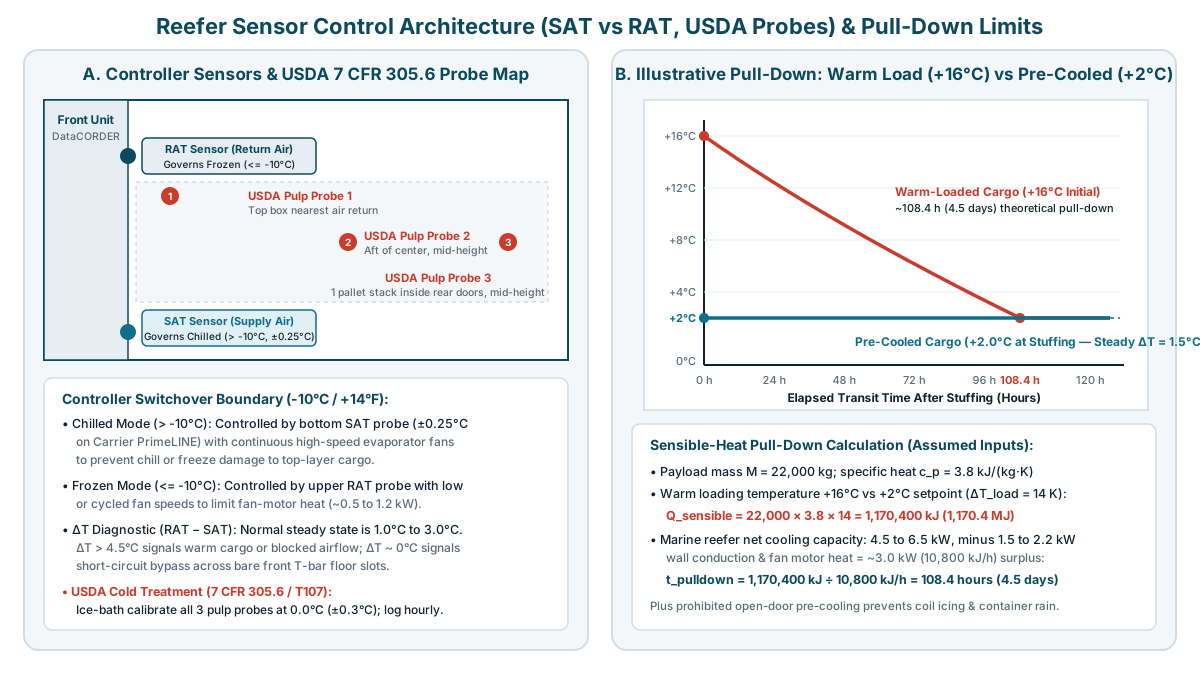
Assume a net cargo mass M = 22,000 kg of chilled fruit or vegetables with a specific heat capacity c_p = 3.8 kJ/(kg·K) loaded at a core pulp temperature T_initial = +16.0°C instead of its required T_setpoint = +2.0°C (ΔT_load = 14.0 K):
- Sensible heat to remove:
22,000 kg × 3.8 kJ/(kg·K) × 14.0 K = 1,170,400 kJ(1,170.4 MJ). - Available surplus cooling rate after wall conduction, fan motor heat, respiration heat at elevated pulp temperature, and periodic electric defrost cycles: assume
P_net = 3.0 kW = 10,800 kJ/h. - Theoretical minimum pull-down time under uniform airflow:
t = 1,170,400 kJ ÷ 10,800 kJ/h = 108.4 hours(4.5 days).
Even under ideal airflow distribution, the unit needs four and a half days just to remove the initial loading heat. In an actual container where carton walls resist heat transfer, center pallets in a warm-stuffed load often remain 4°C to 8°C above setpoint for 6 to 10 days, accelerating respiration, moisture loss, and spoilage.
Why pre-cooling an open container at an ambient dock is prohibited
Ocean carrier handling rules, including the Ocean Network Express (ONE) Refrigerated Cargo Handling Guideline, strictly separate cargo pre-cooling from container pre-cooling. Cargo must always be pre-cooled inside a cold-storage room before stuffing. Pre-cooling the empty reefer container itself is permitted only when the container doors are sealed directly against an enclosed, refrigerated warehouse dock via an inflatable dock shelter (“cold tunnel”).
If a shipper pre-cools an empty container to +2°C or -18°C and then opens the rear doors at an unconditioned ambient dock or yard (for example, +30°C ambient air at 75% relative humidity, which has a dew point of +25.1°C and holds 20.4 g/m³ of water vapor across 67.5 m³ of internal air volume), two failure modes occur immediately:
- Warm humid air contacts the sub-dewpoint aluminum ceiling and sidewalls, condensing into liquid water droplets that drip onto the top layer of corrugated cartons (“container rain” or “container sweating”), softening box board and reducing vertical compression strength.
- When the refrigeration unit restarts after the doors close, that entrained moisture freezes rapidly onto the cold evaporator coil fins. Ice bridges across the fin spacing restrict airflow from the bottom discharge plenum, forcing the unit into repeated 20- to 35-minute electric heater defrost cycles during the first 24 hours of transit.
Bottom-air T-floor circulation vs top-air highway trailers
Loading teams accustomed to domestic trucking often apply highway trailer pallet patterns to ocean containers, causing severe temperature excursions. A 53 ft highway reefer trailer and an ISO marine reefer container move air in opposite directions, as shown in the schematic below and detailed for domestic vans in our 53 ft trailer pallet capacity and airflow guide.
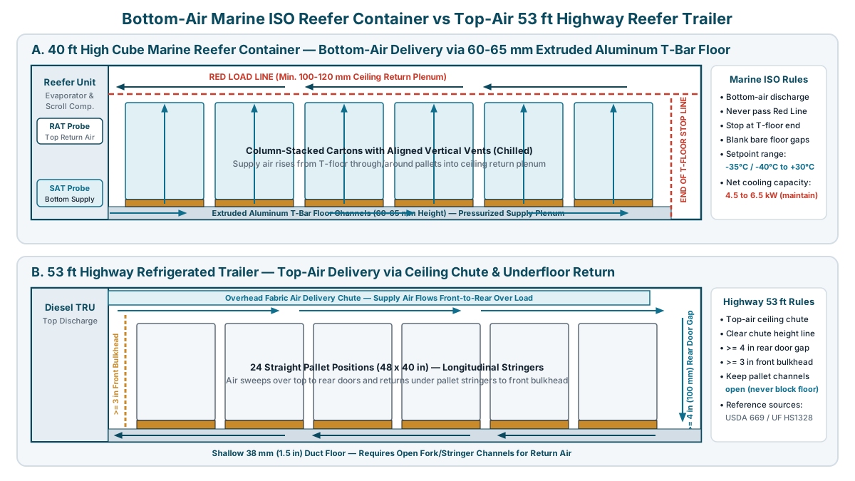
In a marine ISO reefer container, the evaporator fans sit behind the front bulkhead and pressurize the space beneath the cargo. Conditioned supply air discharges from the bottom of the unit into an extruded aluminum T-bar floor whose channels stand 60 to 65 mm (2.4 to 2.6 in) high. That pressurized air travels along the T-floor toward the rear doors, rises vertically through and around the palletized cartons, sweeps horizontally back toward the front along the ceiling clearance space above the painted Red Load Line, and re-enters the upper return-air grille.
In a 53 ft highway reefer trailer (described in USDA AMS Agriculture Handbook No. 669 and UF/IFAS Extension publication HS1328), the cycle is inverted: conditioned air leaves the top of the front refrigeration unit through a ceiling chute, flows horizontally over the top of the load to the rear doors, drops down the rear door gap, and returns forward underneath the pallets along a shallow 38 mm (1.5 in) duct floor to the lower front bulkhead.
Table: scroll horizontally if needed to see every column.
| Engineering parameter | 40 ft High Cube (40’ HC) marine ISO reefer | 53 ft highway refrigerated trailer | Operational consequence if rules are mixed |
|---|---|---|---|
| Supply air discharge location | Bottom of front bulkhead directly into extruded T-bar floor channels (60 to 65 mm height) | Top of front bulkhead via ceiling-mounted fabric air delivery chute | Leaving bare floor gaps in a marine container vents pressurized supply air before it reaches the rear doors |
| Return air intake location | Upper front bulkhead grille above the evaporator baffle plate | Bottom of front bulkhead behind a return-air bulkhead spacer (>= 3 in / 75 mm clearance) | Stacking cargo to the ceiling in a marine container blocks the upper return path entirely |
| Maximum stack height limit | Painted Red Load Line 100 to 120 mm (4 to 4.7 in) below the corrugated ceiling | Below the overhead air chute line (inside height typically 104.1 to 105.5 in) | Over-line cartons create a stagnant heat pocket across the rear half of the container |
| Rear door clearance boundary | Cargo must stop at the End-of-T-Floor line before the rear door sill channels end | Leave >= 4 in (100 mm) rear door clearance so top air can turn downward under the load | Extending cargo past the T-floor blocks the rear vertical air loop inside the door corrugations |
| Operating setpoint envelope | -35°C to +30°C on Carrier PrimeLINE; -40°C to +30°C on Thermo King MAGNUM PLUS | Typically -29°C (-20°F) to +27°C (+80°F) depending on trailer insulation and diesel TRU | Deep-frozen seafood or biopharma below -30°C requires a verified marine unit specification |
Why bare T-bar floor channels cause airflow short-circuiting
Pressurized air inside the T-bar floor plenum follows the path of least aerodynamic resistance, where pressure drop scales with flow resistance times the square of volumetric flow (ΔP ∝ R_flow × Q²). The cargo bed above the T-floor acts as a porous resistance plate. If the pallets do not cover the entire floor area (for example, when standard 48 × 40 in / 1219 × 1016 mm or Euro 1200 × 800 mm pallets leave a center aisle gap between rows or an unstuffed strip between the last pallet row and the End-of-T-Floor line), the pressurized supply air escapes straight up through the open T-floor slots and loops back to the upper return grille without passing through the rear pallets.
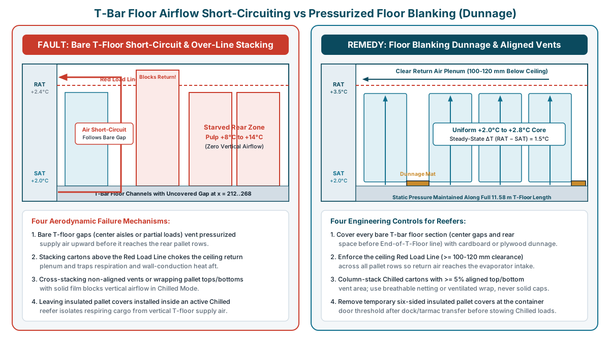
To maintain static pressure underneath the entire 11.58 m internal floor length of a 40’ HC reefer, loaders must apply floor blanking dunnage (corrugated cardboard sheets, fibreboard, or plywood filler mats taped or wedged flat over the T-bars) across every uncovered floor section:
- Cover the open T-bar floor strip between the final pallet row and the End-of-T-Floor line near the rear doors.
- Cover any longitudinal center gap between left and right pallet rows when pallet widths leave an open channel down the middle of the floor.
- Never place solid plastic slip-sheets or unvented cardboard beneath the pallets themselves when shipping in Chilled Mode, where supply air must enter through the pallet base and carton vents.
Chilled Mode (Supply Air) vs Frozen Mode (Return Air) and ΔT diagnostics
A marine reefer unit does not control temperature the same way at +2°C as it does at -20°C. Per the Carrier Transicold Operations and Service Manual (T-363) and Thermo King controller architecture, the microprocessor automatically switches its governing control sensor and evaporator fan speed at the -10°C (+14°F) setpoint boundary. Understanding which sensor governs the unit is essential when comparing reefer download files against independent pallet loggers in a shipment temperature chart review or a frozen food temperature baseline study.
1. Chilled / Perishable Mode (setpoints above -10°C / +14°F)
When the setpoint is above -10°C (such as +0.5°C for berries, +2°C to +8°C for pharmaceuticals, or +13.3°C for bananas), the controller regulates cooling capacity using the Supply Air Temperature (SAT) sensor mounted in the bottom discharge plenum directly below the evaporator coil. On a Carrier PrimeLINE unit with digital scroll unloading, SAT is held within ±0.25°C (±0.45°F) of setpoint, while the evaporator fans run continuously on high speed (delivering roughly 50 to 60 empty-container air changes per hour) to strip respiration heat and flush carbon dioxide and ethylene when fresh-air makeup vents are open.
Controlling by Supply Air protects chilled cargo from freezing or chill injury. If the unit controlled by Return Air on a warm chilled load, the compressor would discharge sub-freezing air (-4°C to -8°C) into the bottom T-floor to pull the return air down to +2°C, freezing the bottom cartons across the entire container floor.
2. Frozen Mode (setpoints at or below -10°C / +14°F)
When the setpoint is at or below -10°C (typically -18°C to -35°C for frozen food, seafood, or plasma, and down to -40°C on a Thermo King MAGNUM PLUS), the controller switches to the Return Air Temperature (RAT) sensor located behind the upper return grille. Evaporator fans operate on low speed or cycle with compressor demand so the fan motors do not inject unnecessary electrical heat into the cold box.
Because solidly frozen cargo has zero biological respiration and cannot suffer chill injury from supply air that is 2°C to 4°C colder than the setpoint, governing by Return Air guarantees that the warmest air returning from the perimeter of the load never rises above the frozen ceiling (for example, -18.0°C RAT with SAT discharging at -20.5°C).
3. USDA APHIS Phytosanitary Cold Treatment (7 CFR § 305.6 / Schedule T107)
For imported or exported fresh fruit subject to quarantine cold treatment under 7 CFR § 305.6 and Carrier PrimeLINE Service Manual T-372, Section 7.22.5, air sensors alone do not satisfy quarantine release. The fruit must be pre-cooled to or below the treatment threshold before the treatment clock can start, and three calibrated USDA pulp temperature probes must be inserted directly into fruit flesh at three mandated container locations:
- Position USDA Probe #1 inside the top layer of a fruit carton nearest the upper return-air intake at the front bulkhead.
- Position USDA Probe #2 inside a fruit carton slightly aft of the longitudinal center of the container at mid-stack height.
- Position USDA Probe #3 inside a fruit carton one pallet stack inward from the rear doors at mid-stack height.
Before stuffing, all three pulp probes must be calibrated in a clean 0.0°C (32°F) crushed-ice water slurry and verify within ±0.3°C (±0.5°F) of 0.0°C, following the verification principles described in our calibration certificate review guide. The container’s tamper-resistant DataCORDER logs all three pulp probes alongside SAT and RAT at 60-minute intervals. If any single pulp probe rises above the schedule ceiling during the 14- to 22-day treatment period, the quarantine clock resets or extends.
Table: scroll horizontally if needed to see every column.
| Operating mode | Setpoint range | Governing sensor | Fan speed & fresh-air vents | Normal steady-state ΔT (RAT − SAT) | Diagnostic meaning of abnormal ΔT |
|---|---|---|---|---|---|
| Chilled / Perishable Mode | Above -10°C (+14°F); typically -1.5°C to +15°C | Supply Air Temperature (SAT) at bottom discharge (±0.25°C) | Continuous high speed; fresh-air vents open (15 to 150+ m³/h) for respiring produce, closed (0 m³/h) for pharma/non-respiring | 1.0°C to 2.5°C (up to 3.0°C on high-respiration fruit) | Persistent ΔT > 4.0°C to 5.0°C indicates warm-stuffed cargo or restricted vertical airflow; ΔT near 0°C while cargo is warm indicates T-floor short-circuiting |
| Frozen Mode | At or below -10°C (+14°F); -18°C to -35°C / -40°C | Return Air Temperature (RAT) at upper intake grille (±0.5°C to ±1.0°C) | Low speed or cycled; fresh-air vents strictly closed (0 m³/h) to prevent moisture ingress and coil icing | 1.5°C to 3.0°C during cooling cycles | RAT holding at setpoint while rear pallet loggers drift upward indicates a blocked Red Load Line return plenum or unblanked front T-floor gap |
| USDA Cold Treatment (7 CFR 305.6) | Typically 0.0°C to +2.22°C (32°F to 36°F) pulp ceiling | SAT control (set 0.6°C to 1.1°C below max pulp limit) + 3 USDA pulp probes | Continuous high speed; vents set per commodity CO2 tolerance | 0.8°C to 2.0°C across entire treatment window | USDA #3 (rear door probe) lagging > 1.5°C warmer than USDA #1 indicates supply air escaping through bare T-floor channels before reaching the rear row |
Pallet stowage patterns, carton venting, and when to remove insulated pallet covers
In cold chain shipping, packaging design and container aerodynamics interact directly. A carton or pallet shroud that protects cargo on an ambient loading dock can block heat removal once stowed inside an active container. Teams should separate the primary product pack, the outer shipping case, and the transport enclosure as outlined in our chilled and frozen food packaging guide and active versus passive systems comparison.
Vertical airflow (Chilled) vs perimeter blanket airflow (Frozen)
- In Chilled Mode (“through-the-load” vertical airflow), respiring produce generates internal heat continuously and pharmaceuticals require tight spatial uniformity, so conditioned air from the T-floor must pass vertically up through the interiors of the cases. Cartons must have at least 5% aligned top-and-bottom vent area and be column-stacked (register-stacked) so the vent holes form continuous vertical chimneys from the pallet deck to the top of the stack. Never cross-stack (interlock) cartons whose top and bottom vents do not align in both orientations, and secure pallets with breathable horizontal netting, corner boards, and strapping rather than sealing the top or bottom of the pallet with solid polyethylene stretch film.
- In Frozen Mode (“around-the-load” perimeter blanket airflow), solidly frozen cartons generate no internal heat; the refrigeration unit only needs to intercept external heat conducting through the container walls, roof, and floor before that heat reaches the cargo. Frozen cases are packed in solid, non-vented cartons and stowed in a tight, center-braced block stow so cold air circulates smoothly under the T-floor, up the sidewall corrugations, and back across the ceiling return plenum.
Operational rule for insulated pallet covers and thermal blankets
Reflective bubble-foil insulated pallet covers and phase-change material (PCM) thermal blankets are engineered for bounded, unrefrigerated transfer intervals such as cross-dock staging, yard transfers, or airport tarmac ramps, as analyzed in our insulated pallet covers and thermal blankets comparison. According to Pharma.Aero’s Airside Transportation Survey (Section 4.3.1), a thermal blanket should be applied to pre-conditioned pallets inside a temperature-controlled room before staging, enclose all six sides (including the pallet base against ground radiation), and be removed once the ambient exposure ends.
Leaving a vapor- and airflow-impervious insulated pallet cover wrapped around a pallet inside an active Chilled reefer container blocks the upward T-bar floor airflow from entering the pallet base. For respiring chilled produce, the cover acts as a greenhouse shroud, trapping biological respiration heat inside the pallet and driving core temperatures upward despite sub-zero or +2°C container supply air. For non-respiring pharmaceuticals or mixed-temperature cargo, an insulated pallet cover should remain installed inside an active reefer only when a written lane qualification study (see spatial temperature mapping versus routine monitoring) explicitly specifies a sealed passive shroud to buffer defrost spikes or door-opening transients.
Table: scroll horizontally if needed to see every column.
| Cargo thermal regime | Carton vent design & stacking pattern | Pallet wrap & T-floor interface | Floor dunnage blanking rule | Insulated pallet cover rule at stuffing |
|---|---|---|---|---|
| Chilled respiring produce (+0.5°C to +14°C) | Column-stacked cartons with >= 5% aligned top-and-bottom vent openings | Breathable horizontal netting or perforated wrap; pallet base and top strictly open | Blank all bare T-floor gaps at rear door threshold and center aisle with cardboard/plywood mats | Apply six-sided cover in cold storage for ambient yard/dock transfer (15 to 45 min), then remove cover at container door before stowing |
| Chilled pharmaceuticals (+2°C to +8°C) | Validated case layout per lane mapping study; maintain uniform vertical and perimeter channels | Perforated or banded wrap keeping bottom fork/deck channels open unless qualified as passive shippers | Blank exposed T-floor channels so supply air circulates uniformly to rear doors | Remove ramp cover before stowing in active container unless a documented lane qualification specifies a sealed shroud for door/defrost buffering |
| Frozen food & biopharma (-18°C to -40°C) | Solid non-vented cartons; tight center-braced block stow (“blanket cooling”) | Standard stretch wrap permitted on sides; keep T-floor channels and wall corrugations clear | Blank open T-floor area behind last pallet row if partial load leaves rear floor bare | Remove ramp cover at stuffing so perimeter return air can sweep heat away from outer pallet faces |
Copyable pre-stuffing and reefer handover inspection record
Use this inspection record alongside the warehouse dispatch handover checklist to verify the container, the cargo core temperature, and the airflow path before signing the bill of lading or equipment interchange receipt.
Table: scroll horizontally if needed to see every column.
| Inspection stage & field | Verification requirement | Recorded value & evidence reference |
|---|---|---|
| Container ID, ISO size & unit model | Record container number, 20’ / 40’ HC type, and refrigeration unit make/model (verify -35°C or -40°C capability if deep-frozen) | ______ |
| Pre-Trip Inspection (PTI) & cleanliness | Confirm current PTI sticker/log, odor-free interior, intact door gaskets, unobstructed T-bar floor channels, and clear bottom condensate drains | ______ |
| Cargo pulp temperature prior to stuffing | Measure and record core product / pallet temperature inside cold storage before moving to dock; reject warm cargo for blast pre-cooling | ______ |
| Dock environment & pre-cooling rule | Confirm empty container is NOT pre-cooled with doors open in humid ambient air; run unit during stuffing only inside a sealed refrigerated dock tunnel | ______ |
| Setpoint, control mode & fresh-air vents | Verify controller setpoint (°C/°F), governing mode (SAT > -10°C vs RAT <= -10°C), dehumidification setting, and fresh-air vent position (0 m³/h for frozen/pharma; specified m³/h for produce) | ______ |
| Insulated pallet cover removal check | If six-sided insulated pallet covers were used for ambient yard/dock transfer, confirm removal at container door threshold prior to stowing (unless required by written lane qualification) | ______ |
| Red Load Line & End-of-T-Floor check | Verify every pallet top sits below the painted ceiling Red Load Line (>= 100 to 120 mm clearance) and stops at or before the End-of-T-Floor line | ______ |
| Bare T-floor dunnage blanking | Confirm cardboard or plywood blanking sheets cover all open T-floor slots in center gaps and behind the last pallet row, with photograph attached | ______ |
| Probe placement & calibration (if applicable) | Record independent data logger IDs/locations or USDA #1, #2, #3 pulp probe positions and 0.0°C ice-bath calibration offsets (±0.3°C) | ______ |
| Post-closing ΔT stabilization & seal | Close doors, start unit, record initial SAT and RAT, verify seal number, and assign transit/arrival chart review owner | ______ |
Dock supervisor pre-dispatch checklist
- Container T-bar floor swept clean of debris, broken wood splinters, and shrink-wrap tails; corner drain holes verified clear.
- Product core pulp temperature measured and confirmed at or below target transport setpoint before leaving cold storage.
- Refrigeration unit switched OFF while rear doors are open at an unconditioned ambient dock to prevent evaporator coil icing and ceiling condensation (“container rain”).
- Temporary six-sided insulated pallet covers removed at the container threshold before loading respiring chilled pallets onto the T-bar floor.
- Cartons column-stacked with aligned top-and-bottom vents for Chilled Mode, or tightly block-stowed for Frozen Mode.
- All bare T-bar floor channels (center gaps and rear threshold space) covered with corrugated cardboard or plywood dunnage mats.
- Full load verified below the ceiling Red Load Line (100 to 120 mm clearance) and forward of the End-of-T-Floor rear door line.
- Controller setpoint, fresh-air vent opening (m³/h or CFM), USDA pulp probes (if applicable), and independent pallet loggers verified and photographed prior to sealing.
Frequently asked questions
Why does a reefer container control by supply air in chilled mode and return air in frozen mode?
Above -10°C (+14°F), a marine reefer operates in Chilled (Perishable) Mode and regulates cooling capacity using the bottom Supply Air Temperature (SAT) sensor within ±0.25°C so the discharge air never drops below the freezing or chill-injury threshold of sensitive produce or 2°C to 8°C pharmaceuticals. At or below -10°C, the unit switches to Frozen Mode and controls by the upper Return Air Temperature (RAT) sensor with low evaporator fan speed, because solidly frozen cargo cannot be damaged by colder supply air and RAT control ensures the warmest air returning from the container perimeter stays at or below the frozen setpoint.
Can you pre-cool warm cargo inside a marine reefer container after loading?
No. A 40 ft High Cube marine reefer delivers only 4.5 to 6.5 kW of total net cooling capacity at standard transport conditions, and 1.5 to 2.2 kW of that capacity is consumed continuously by heat conduction through the container walls and evaporator fan motor heat. Removing 14 K of excess field heat from a 22,000 kg chilled load requires more than 108 hours (4.5 days) under ideal uniform airflow, and often 6 to 10 days inside stacked cartons, causing severe shelf-life loss, condensation, and high return-to-supply temperature differentials.
Why is pre-cooling an empty reefer container with open doors at an ambient dock prohibited?
When a pre-cooled container’s doors are opened in warm, humid ambient air, moisture condenses immediately on the cold aluminum ceiling and walls (“container rain”), wetting and weakening top-layer corrugated cartons. As soon as the unit restarts, that humid air freezes onto the evaporator coil fins, restricting bottom T-bar floor airflow and forcing repeated electric defrost cycles that spike internal air temperatures during the first 24 hours of transit.
Should insulated pallet covers stay on pallets inside an active reefer container?
For respiring chilled cargo and standard ventilated container loads, six-sided insulated pallet covers and thermal blankets should be applied inside cold storage to protect pallets during 15- to 45-minute unconditioned dock, yard, or tarmac transfers and removed at the container door before stowing. Leaving an impervious cover on a pallet inside a Chilled reefer blocks upward T-bar floor supply air from passing through the cartons and traps respiration heat inside the shroud, unless a written lane qualification specifically validates a sealed passive-in-active configuration for non-respiring goods.
Method and sources
This guide compiles equipment specifications, microprocessor control rules, and stowage standards from primary manufacturer manuals, ocean carrier handling guides, and federal agricultural regulations accessed on 25 October 2026:
- Marine refrigeration unit operating ranges, net cooling capacities, and sensor control boundaries (-10°C / +14°F switchover between Chilled SAT control and Frozen RAT control) come from the Carrier Transicold PrimeLINE specifications, the Carrier PrimeLINE technical brochure 62-11248, the Carrier Operations and Service Manual T-363, the Thermo King MAGNUM PLUS specifications, and the Thermo King MAGNUM PLUS brochure TK80045.
- T-bar floor airflow mechanics, Red Load Line and End-of-T-Floor clearances, floor dunnage blanking, and the prohibition of open-door container pre-cooling come from the Ocean Network Express (ONE) Refrigerated Cargo Handling Guideline Brochure.
- Quarantine cold treatment pulp probe placements (USDA #1, #2, and #3), 0.0°C ice-slurry calibration tolerances (±0.3°C), and hourly DataCORDER logging requirements come from 7 CFR § 305.6 and Carrier PrimeLINE Service Manual T-372, Section 7.22.5.
- Highway trailer versus marine container airflow comparisons and pallet stringer/venting practices come from USDA AMS Agriculture Handbook No. 669, UF/IFAS Extension publication HS1328, and the IRTA / GCCA Refrigerated Transportation Best Practices Guide v2.0.
- Six-sided thermal blanket application and removal boundaries during ambient ramp and cross-dock transfers come from the Pharma.Aero Airside Transportation Survey White Paper, Section 4.3.1.
The sensible-heat pull-down calculation uses stated illustrative inputs (M = 22,000 kg, c_p = 3.8 kJ/(kg·K), ΔT = 14 K, and 3.0 kW surplus cooling rate) to demonstrate the thermodynamic capacity balance; verify specific container heat leakage and commodity respiration rates against your carrier’s technical datasheet and lane qualification protocol.
Prepared by Cold Chain Practice Editorial Desk.
Related guides
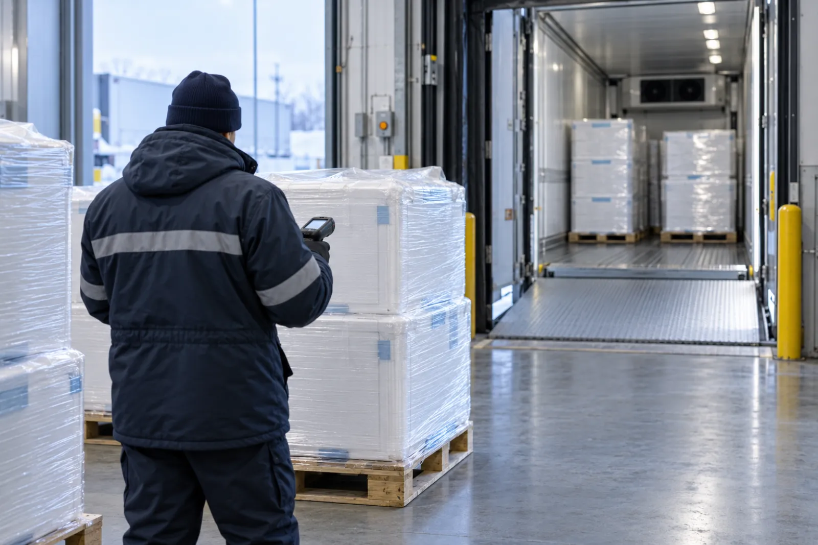
Temperature-Sensitive Dispatch: A Warehouse Handover Checklist
A cold chain dispatch checklist covering pick checks, logger start, documents, carrier handover, data responsibility and exception escalation fields.
Read guide How Many Pallets Fit in a 53 ft Trailer? Dry Van vs Reefer, Single vs Double Stacked
Pallet counts for a 53 ft dry van or reefer, worked from inside dimensions: 48 x 40 in orientation, reefer airflow gaps, and double-stack height and weight.
Read guide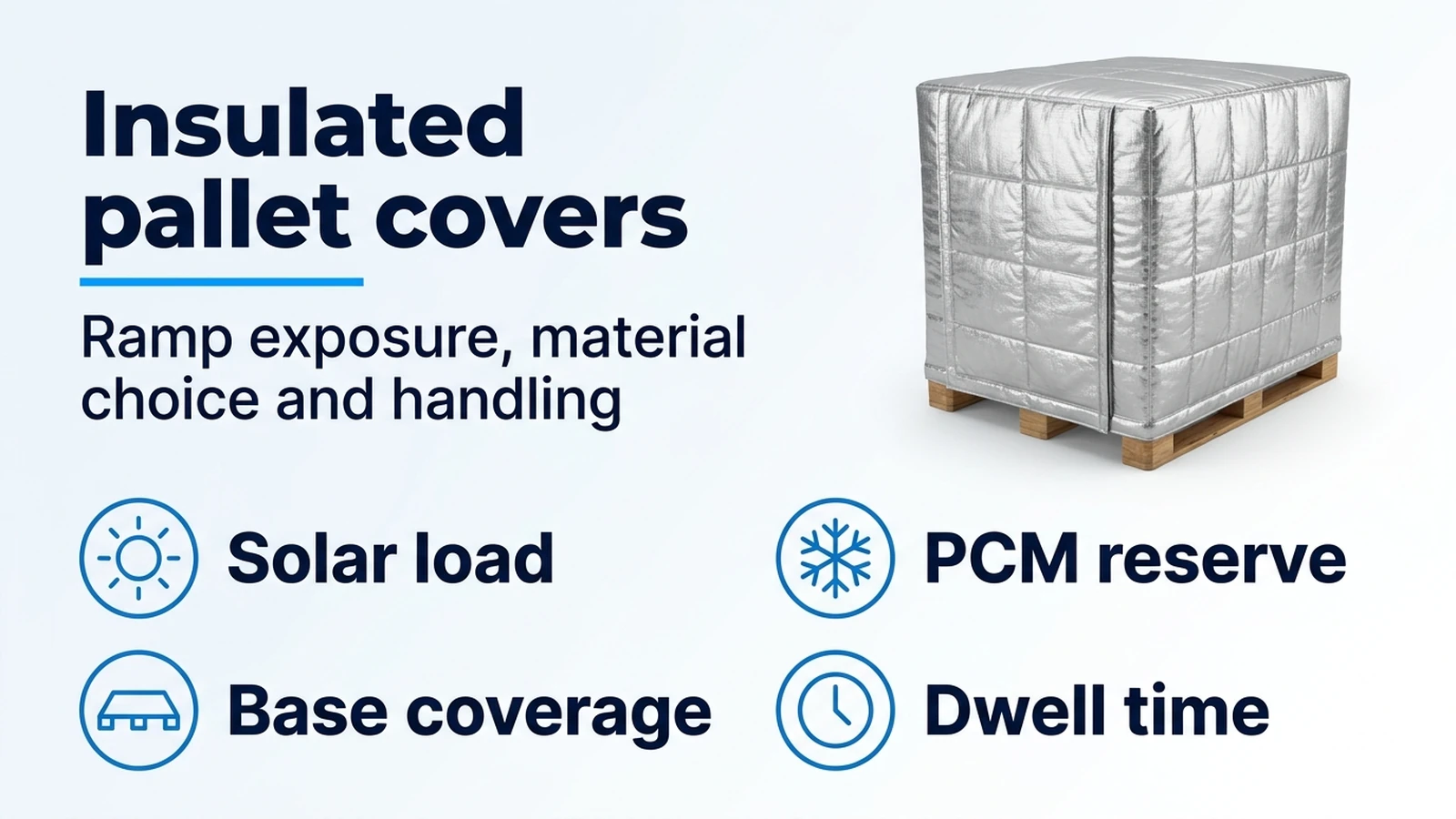
Insulated pallet covers and thermal blankets: compare ramp protection
Compare reflective bubble-foil and PCM pallet covers for dock, tarmac and yard exposure, including solar load, handling costs and limits of 7E-style evidence.
Read guide
Temperature Mapping vs Shipment Monitoring: Different Questions, Different Evidence
Separate facility temperature mapping from shipment monitoring: the questions each answers, the evidence each produces and where buyers mix them up.
Read guide